
Till now we completed the basic but major part of Analog Electronics. I hope you really enjoyed my posts and my courses as well. In this post, we will see the concept of current mirror circuits and it's application. I had seen most of the students struggling with the significance of the current mirror circuit, so I will try my best to explain the concept and the significance, i.e. why we are using the current mirror circuit and when we need it.


Before starting the concept let me ask you one question, let's suppose I have one load resistance assume resistance as RL = 10Kohms, and to that load, I need to provide a fixed amount of current, assume the value of current as I = 1mA. So what process do you follow to provide fix amount of current?
So you will tell me it is very simple, we know the value of current i.e. I = 1mA, and the value of resistance RL = 10Kohms based on this information we can easily calculate the voltage.
Therefore Voltage(V) = I * RL = 1mA * 10Kohms = 10V
So we need to provide 10V to the load resistor as shown below.

I will say theoretically it is correct but practically the value of current may change as it depends on various factors like temperature, the internal resistance of voltage source, wires, etc.
Let's suppose the internal resistance of the 10V voltage source is 100ohms.
Now, the effective resistance is 10Kohms plus 100ohms i.e. R = RL + R1 = 10k + 100 = 10.1kohms.
As the overall resistance increases, the value of current decreases
i.e. I = 10/10.1k = 0.9mA

So there is a drop of 0.1mA which may look very small almost negligible to you but now think we are designing an Ic and there might be many such circuits so eventually this small drop in current adds up to provide a huge drop.
So to overcome this issue we make use of a current mirror circuit which provides a fixed amount of current in a circuit irrespective of the value of the load resistance.

Now, let's suppose we want to provide a voltage source to any circuit we can easily do that by connecting desired volts of battery to that circuit.

But in the case of the current source we cannot do so as it is not available readily in the market we need to design it and implement it in a circuit.

So I hope you understood the significance and importance of the current mirror circuit although the application part is still pending which I will cover at the end of this post. Now, we will proceed to the designing part.
Since we want a current source to be independent of the load resistor and temperature thus we need to take great care of these parameters. In the previous post, we had seen that we can do this by biasing BJTs. Generally, two techniques are employed when it comes to biasing of BJTs that is a collector to
base bias and voltage divider bias. We know that the current mirror circuits are mostly used in integrated circuits and the size of the integrated circuits must be as less as possible.
Now, as voltage divider biasing techniques require more resistor as compared to the collector to base bias and resistance of any resistor is directly proportional to the length or size thus implementing voltage divider biasing technique may consume more space so to overcome this issue we make use of collector to base biasing technique. But we do not connect the base resistor to the base terminal of BJT (i.e. RB = 0) the reason is discussed below.

Another reason to go with the collector-to-base bias is that we know that for BJT to act as an amplifier, the base-emitter junction should operate in the forward bias mode and the base-collector junction in reverse bias mode. Thus by shorting the base and collector junction we ensure that the base-collector junction operates in the reverse bias condition and the base-emitter region operates in forward bias condition.

Now, since we want a constant current source so to generate that we connect the base of the second BJT to the biased BJT as shown below. The biased BJT will assure that the current Iin is independent of temperature. But the most important point over here is that both the BJTs should be exactly identical meaning the specifications of both the BJTs should be similar.

Traditionally we use to provide an input signal to the base terminal of BJT but over here we are providing the input signal that is current Iin to the collector of the biased BJT and the output current Iout is now dependent on Iin it is no longer function of beta and temperature. So the main intention or aim of this circuit is that Iout = Iin
The images below will show you the derivation that how exactly the Iout is totally dependent on Iin.


# Application of Current Mirror Circuits:-
1) It is used in Differential Amplifiers:-

The current source is connected between the emitter and voltage -Vee to reduce the common-mode gain of the Differential Amplifier.
I will explain the above point in the Differential Amplifier post.
2) Can be used as an Active Load:-

The resistance of the 2nd BJT connected in the circuit from which the Iout flows is high. We know that the early effect voltage is high (maybe 40v-50v). Therefore, Rout = Va/Iout
where Va is the early effect voltage and
Iout is the output current.
3) It is used in ICs to establish a biasing point of different amplifiers present in the ICs:-

Now there are many different amplifiers present in an IC. So it is impossible to design a separate current mirror circuit for each and every amplifier therefore all the amplifiers present in ICs are biased in such a way that their Q-point is almost similar.
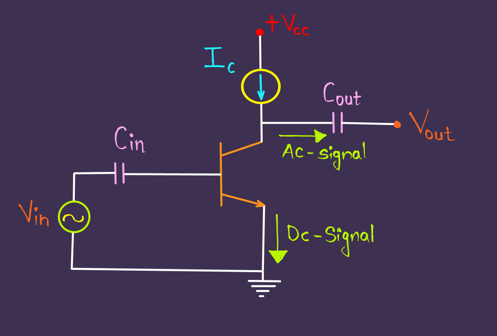
Now, we will try to see how amplifiers are designed inside ICs with few resistors. While designing an amplifier using a single BJT we use it to connect the capacitor parallel to the emitter resistor to reduce the noisy signal but in ICs it is difficult to fabricate and implement capacitors so for minimal use of capacitors, we make use of Current Mirror Circuits.
We know that the Voltage Gain of a Ce amplifier roughly is Av = -Rc / Re
Since Re = 0 therefore Av will be infinite (ideally) but very high practically.
As discussed above current sources have high resistance (active load concept) thus by using current mirror circuits we are not only providing a stable bias point but also high gain.
4) Current Sources are used to charge the batteries:-

Some batteries require a constant current source to charge thus it can be implemented by a current mirror circuit.
I hope you not only understood the concept in-depth but also its application and significance.
Influencers gone wild bring pure creativity to life. Their fun, fearless content and authentic confidence make the internet a much more enjoyable place for everyone watching.
ReplyDeleteThis comment has been removed by the author.
ReplyDeleteFoxNewsPaper delivers exceptionally detailed coverage across politics, business, and entertainment. Their dedication to providing timely updates and in-depth analysis ensures readers stay well-informed about global events, making it a reliable source for anyone seeking trusted news daily.
ReplyDeleteHDHub4u’s reviews with ratings are perfect for movie enthusiasts. Their honest 3/5 review saved me from wasting time on a dull film.
ReplyDelete